At Doty Scientific, “commitment to service” is not an empty slogan. Years ago it was determined that service needed top level direction. For assistance, please contact us at service@dotynmr.com
Frequently Asked Questions
General
Yes. We have had a European Sales and Service office for many years. Presently, the authorized service center is in Germany. ROTOTEC SPINTEC will be able to help with service of Doty products in Europe.
We have additional sales representatives, RS2D in France and Belgium, LA Systems in Japan, and BK Instruments Inc., in South Korea.
Check out our Foreign Distributors Page under Contact Us for the information you need on these sales and service representatives.
You can call us at (803) 788-6497 and talk to Dave McCree, or sometimes Laura Holte our sales manager at(803) 738-6832 can assist you. If you prefer email, service@dotynmr.com. If you need to send a fax, (803) 736-5495.
If you have questions about specifications, call Laura Holte, our sales manager at (803)738-6834), or you can call us at (803) 788-6497. It is best to ask for Dave McCree.
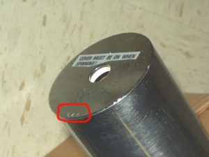
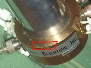
First, contact us about the problem. Call or email us with a description of the problem. It is important to provide the name of your institute, and the Doty probe or coil serial number. (The serial number starts with “DSI-“ and is usually located on our probes where shown below.) The serial number can be found on the cover of your manual. If the probe needs to return to Doty for repair, we will allot a RMA (return material authorization) number for it.
Enclose a letter with the probe detailing the problem, the associated RMA number, and contact information including a contact person and phone, email, address. Please also send all tuning elements of the probe back so that tuning for all nuclei can be checked during repair. It saves time later if you also enclose the address for return of the item after repair.
It is important to check with your country’s customs office or your customs broker. Sometimes there are special forms that you need to fill out before returning an item. (It may be helpful to have one of our international sales or service representatives help you with the customs, if the probe has to come back to the United States.)
It is very important to write on your waybill, commercial invoice and on any other paper work: ” Goods made in the United States being returned to manufacturer for service or repair. No Duties or Taxes are due.”
Our shipping address is:
Doty Scientific, Inc,
700 Clemson Rd.
Columbia, SC 29229
USA
Yes, we do require prior authorization. Please contact us for a RMA number before shipping the probe and tuning elements to us for repair. Also, be sure to include full contact information, Doty probe (or coil) serial number information and a complete description of problems on paper in the box with the product to avoid unnecessary delays.
Technical Information / Troubleshooting
The most common problem with spinning is poorly packed or balanced samples. Samples should be finely powdered to avoid more massive lumps positioned asymmetrically on the inside circumference of the rotor. Add the sample to the rotor as evenly as possible and then spin the sample slowly for a couple of minutes to let it “spin pack” before gradually increasing the speed.
Also fairly common with probes that have been in the field for a while is excessive turbine cap wear. Turbine caps wear both from spinning and handling during the loading process. The cap can be looked at under a magnifying glass to look for wear. It would be preferable to compare the cap to a new cap if you have one.
Much less common but still possible in some extremes is excessive rotor wear usually caused by spinning an unbalanced sample for a significant period of time. This usually also causes stator wear and may require a trip to the factory for service of the probe.
If you try to spin an empty rotor and still have problems with a new set of turbine caps then there may be a problem with the probe that will require factory service.
“Spikes” in the FID are asynchronous noise bursts at the observe frequency being generated somewhere in the NMR system. There are several possible sources for this noise including arcing in the probe or sample coil. A bad cable or poor quality cable that has recently been put into the system could cause the problem. Devices external to the probe or sample coil can arc causing the noise. Frequently we find that high power filters in-line before the Doty probe or coil are the source of troublesome noise spikes. To isolate the cause it is a good idea to switch out parts to see if eliminating one part also eliminates the problem. To check the Doty probe or coil for high level arcing an inline directional coupler, which will allow you to see the reflected pulse envelope on an oscilloscope, is very useful. If the probe is arcing then you will see a sudden large jump in reflected power during the pulse at the point of initiation of the arc. The probe can be the source of the noise even if there is no high level arc visible in the reflected pulse envelope. This noise can be caused by a defective ground contact inside the probe and generate no other signs of arcing. If you are convinced after checking the system that the probe is the source of the noise then the best thing to do is send it back to us for evaluation and repair.
There are normally instructions in the user manual for the correct method for your probe. However, some general instructions are:
• Start with about 10 psi of bearing gas pressure.
• Add a couple of psi of drive pressure to get the rotor spinning.
• Gradually increase bearing and drive together keeping bearing 10 to 15 psi higher than drive up to about 40 psi on the bearing.
• After this the drive can be increased faster than the bearing until the drive is equal to or slightly greater than the bearing up to the maximum spinning speed. This should be achievable with less than 60 psi on both drive and bearing gas lines.
• Regardless of the above instructions always listen carefully to the sound of the spinner. If there is a change in pitch quality, this may indicate that more bearing pressure is required.
The user should be aware that there are spinning speed limits that are different depending on the type of rotor, turbine cap and sample being used. Never exceed the speed rating of the slowest component in the spinner system. The speed ratings for various components are given in the user manual and on the MAS Spinning Speed Page .
Homogeneity is sometimes hard to evaluate on the bench and we need to have a quantitative indication to use. Look at the discussion on Coil Lengths for guidelines on what typical field profile to expect in small coils. We recommend a spin-echo mapping method (see S. Crozier, K. Luescher, L.K. Forbes, and D.M. Doddrell, “Optimized Small-Bore, High-Pass Resonator Designs,” J. Magn. Reson. Ser. B , 1995, 109 , 1-11) in which a series of slice-selective spin-echo images are acquired with varying pre-pulse lengths. The pre-pulse lengths should be (2*n*π ) where n is 0,1,2, and possibly 3. The resulting images will have varying degrees of inhomogeneity with rings of light and dark that can be used to quantitatively evaluate B1. Quantitative B1 mapping can also be done using a gradient-echo image, preferably with a flip angle under 60°, if an accurately calibrated grey scale or color scale can be supplied with the image.
First some liquids can be very challenging to spin without leaks and there will be a limit for most methods to the speed that can be achieved before leaks occur. The Doty MAS sealing cells for XC and DI type spinners are the best starting point for these types of samples. We have a variety of sample volumes available and while some volume is always lost in the use of these cells, they will seal for most liquids and keep the sample centered in the RF coil. There are also two material types that will provide a reasonable susceptibility match to most solvents.
Many aqueous samples where sample volume is not limited and B1 homogeneity is not an issue can be spun with normal Kel-f or even Aurum turbine caps up to about 20% of the maximum rated speed for the rotor.
For some of our earlier spinners, O-ring caps are another possible option and will provide a larger sample volume. These caps will usually not stay in very well when used with oily samples.
In some extreme cases in may be necessary to use normal turbine caps and glue them into the rotor with super glue. Boiling the rotor in water afterward will usually cause the glue to release but there is a high probability of damage to the turbine caps, so this should be a last resort used with the expectation of throwing away the caps after use.
Most of our turbine caps are not rated for the full VT range of the probe. GFT caps have the widest VT range. For use at XVT the GFT caps may have to be glued in. Glue the caps into the rotor with a good high temperature epoxy. The caps will then have to be drilled out to remove from the rotor so the caps would definitely be one-time use.
(For some of our early probe models, to achieve spinning at the extreme limits it is necessary to use an axial screw turbine cap in most cases. This is a set of turbine caps with a screw running through the center of the rotor from one turbine cap to the other. This screw is inserted into one of the turbine caps and put into the rotor. The other cap threads onto the screw and is pulled tightly into the rotor at the same time. With this arrangement the caps can not get loose and come out of the rotor while it is spinning.)
Please refer to the MAS Spinner Assembly Materials page for more details concerning rotor and cap choices.
